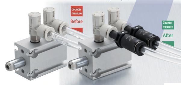
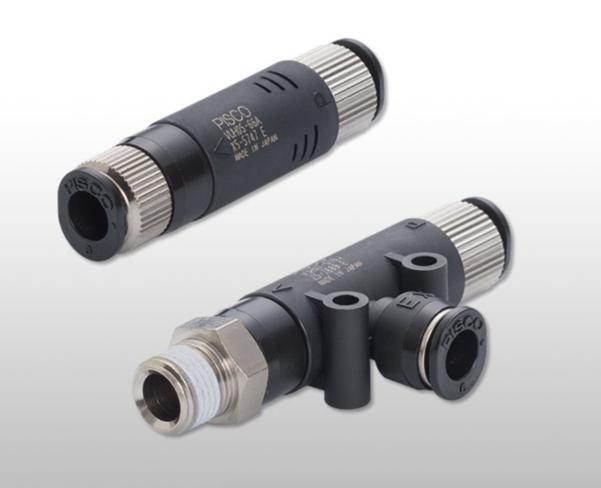
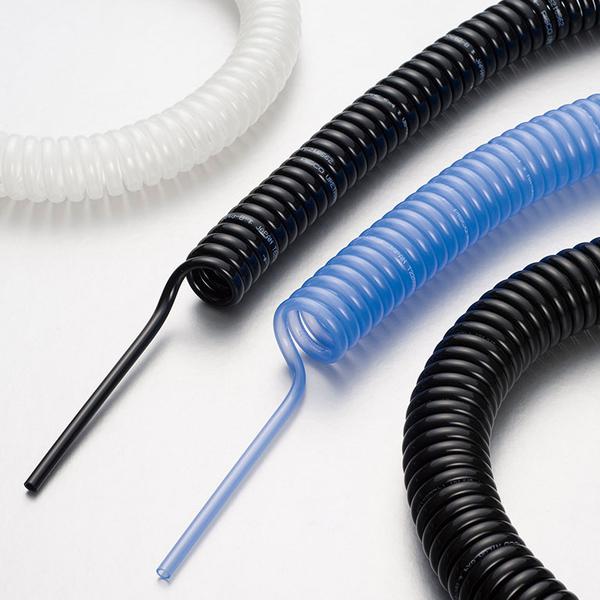
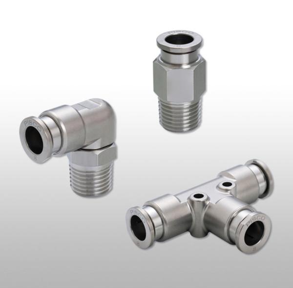
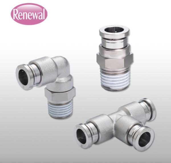
Kanpur
08048073496
+919880566644

pisco pneumatic

68179d65be22ee500d53ff54 Card 2

product image
Pisco Pneumatic

Brass Push-In Fittings – Pisco: Smart, Reliable, Low-Cost Connections for Industrial Systems In pneumatic and fluid handling systems, connection reliability and ease of service are vital. Pisco Pneumatic Straight Fitting, 8 mm x R1/8, PISCO Pneumatic Push‑to‑Connect Elbow Fitting, 6 mm x R1/8, PISCO Pneumatic Push‑to‑Connect Elbow Fitting, 6 mm x R1/4, and similar Pisco push-in fittings deliver durable, leak-proof brass construction with quick, tool-free installation — ideal for both designers and maintenance engineers. These fittings use a push-to-connect (push-in) mechanism that permanently grips pneumatic or fluid tubing (e.g., PU, nylon), creating a secure seal without threaded tools or sealants. Brass bodies, often nickel-plated, offer excellent corrosion resistance and mechanical strength compared to plastic alternatives, making them suited to heavy industrial environments such as automation lines, packaging machinery, machine tools, and pneumatic actuators. Brass fittings also tolerate higher pressures and temperature ranges, enhancing long-term reliability. For design engineers, push-in fittings simplify layout planning with compact shapes, consistent sealing, and compatibility across a broad spectrum of tube sizes and thread standards. They reduce assembly time dramatically, enabling faster prototyping and system builds. For maintenance teams, the one-touch release mechanism shortens service calls, cuts downtime, and minimizes air leakage — a common source of inefficiency in compressed air systems. Quick disconnection and re-use also reduce inventory needs and overall lifecycle cost. Pisco push-in fittings are now widely available in India through authorized distributors like IBK Engineers Pvt Ltd, with stock and support across major industrial centres including Karnataka’s Bangalore region, Pune, Hyderabad, Chennai, and beyond.

68179d65be22ee500d53ff54 Card 2

product image
Pisco Pneumatic

Stainless Steel 316 & PP304 PISCO Fittings: A Practical Guide for Engineers In industrial pneumatic and fluid systems, choosing the right connection components is critical for performance and longevity. PISCO SUS316 Pneumatic Push‑in Straight Fitting, PISCO 12 Φ mm Stainless Steel Fitting Straight, and PISCO 4 Φ mm Stainless Steel Fitting Straight exemplify high-quality fittings engineered for reliability and industrial robustness. 316 stainless steel fittings are ideal where superior corrosion resistance and mechanical strength are required. The addition of molybdenum improves resistance to chemicals, chlorides, and harsh environments, making SS316 excellent for chemical plants, marine, pharmaceutical, and food-grade systems. These fittings maintain structural integrity under high pressure and temperature, helping reduce lifecycle maintenance and minimizing leakage risks in critical applications. PP304 (Polypropylene + SUS304) combinations balance performance and cost. Polypropylene bodies with SUS304 threaded sections provide chemical resistance and reduced weight while allowing visual inspection of fluids in some designs. They are suitable for pneumatic and low-pressure fluid systems where 316 may be over-specified but corrosion resistance is still needed. For design engineers, these PISCO fittings offer versatility in layouts with elbows, tees, and straight connections, and maintenance teams benefit from quick tool-less installation and reduced downtime. Competitive pricing and local availability through distributors ensure cost-effective automation solutions.

68179d65be22ee500d53ff54 Card 2

product image
Pisco Pneumatic

Cleanroom-Ready Pneumatics Components from Pisco: A Guide for Engineers and Maintenance Teams In advanced automation systems—particularly in semiconductor, pharmaceutical, biotech, electronics, and precision assembly sectors—pneumatic components must meet stringent cleanliness, reliability, and performance standards. Pisco, a globally recognized Japanese manufacturer, offers cleanroom-ready pneumatic components engineered to support these demanding environments with excellent integration into robotic systems and automated production lines. Cleanroom-ready variants of Pisco components, including fittings, tubing, and connectors, are manufactured, pre-cleaned, and packaged under controlled conditions to minimize particulate generation and contamination. These components are ideal for ISO-classified cleanrooms or environments where even minute contamination can disrupt processes or damage products. Critical elements include ultra-clean polyurethane and nylon tubes designed for minimal abrasion and outgassing—an important factor for equipment exposed to high-precision robotic handling or vacuum systems. This controlled purity ensures smooth airflow, reduced downtime from contamination, and easier lifecycle maintenance for engineers. For fluid and air distribution, high-quality cleanroom-package fittings such as Pisco PC4‑02 Pneumatic Straight Fitting and PISCO Pneumatic Elbow Connector PL4‑M5 offer compact, leak-resistant connections that simplify machine layout and reduce service time. Advanced flow control valves like Pisco JSC6‑M5A Pneumatic Speed Controller help tune actuator motion precisely—critical for robot end-of-arm tooling and synchronized motion in assembly cells. Additional options such as Pisco Pneumatic Branch Tee and Pisco JSC4‑M5A Pneumatic Speed Controller allow flexible network designs that support modular system upgrades. For design engineers, these cleanroom-ready components mean predictable performance, easier integration with PLC-based controls, and reduced lifecycle costs. Maintenance teams benefit from quick-connect design features, leak-proof joints, and standardized modules, which significantly cut down replacement times and unscheduled downtime. Together, these characteristics make Pisco’s cleanroom pneumatic portfolio a strong choice for modern robotic and automated systems requiring ultra-clean, reliable pneumatic solutions.

68179d65be22ee500d53ff54 Card 2

product image
Pisco Pneumatic

End of Arm Tooling (EOAT) for Robotic Arms End of Arm Tooling (EOAT) refers to the devices mounted at the wrist of a robotic arm that enable the robot to interact with a workpiece. EOAT is a critical element in robotic automation, as overall system performance, accuracy, and reliability depend heavily on correct EOAT design and selection. For design engineers, EOAT must be selected based on payload, part geometry, cycle time, and process requirements. Common EOAT types include mechanical grippers, vacuum suction cups, magnetic grippers, welding guns, dispensing nozzles, and tool changers. Lightweight yet rigid construction is essential to minimize inertia and improve robot speed and positioning accuracy. Materials such as aluminum alloys, stainless steel, and engineering plastics are widely used to balance strength and weight. Modular EOAT designs are preferred, as they allow quick changes and future process flexibility. In applications like pick-and-place, assembly, packaging, and machine tending, vacuum EOAT offers gentle handling of delicate parts, while mechanical grippers provide higher gripping force and repeatability. Tool changers allow a single robot to perform multiple operations, increasing overall equipment effectiveness (OEE). From a maintenance perspective, EOAT should be designed for easy access and quick replacement of wear parts such as seals, suction cups, fingers, and sensors. Standardized fittings, push-in pneumatic connections, and quick-release mechanisms reduce downtime during servicing. Regular inspection of hoses, vacuum lines, fasteners, and sensors ensures consistent performance and prevents unexpected failures. Proper EOAT selection and maintenance directly impact robot uptime, product quality, and safety. By integrating robust EOAT design with preventive maintenance practices, manufacturers can maximize the efficiency, flexibility, and long-term reliability of robotic automation systems.

68179d65be22ee500d53ff54 Card 2

product image
Pisco Pneumatic

3-Jaw Pneumatic Grippers for Automation: A Practical Guide for Engineers In modern industrial automation, 3-jaw pneumatic grippers stand out as versatile end-of-arm tools for robotic handling systems. Designed to provide reliable and balanced gripping, these devices are critical when precision, speed, and repeatability are paramount—especially in assembly, material transfer, and packaging operations. What Is a 3-Jaw Pneumatic Gripper? A 3-jaw pneumatic gripper is a mechanical actuator that uses compressed air to drive three equally spaced fingers or jaws. Unlike two-jaw grippers, the three jaws create a symmetrical grip, improving stability when handling cylindrical or round parts such as shafts, bearings, bottles, and housings. Key Advantages Uniform Load Distribution: The three contact points ensure an even grip around the part, reducing slippage and minimizing deformation of delicate components. High Speed and Repeatability: Pneumatic actuation allows rapid open/close cycles, ideal for high-throughput robotic systems. Simple and Robust Design: Fewer moving parts compared to electric alternatives mean lower initial costs and easier integration. Design Considerations for Engineers When selecting or designing a 3-jaw pneumatic gripper, engineers should consider: Jaw Stroke and Range: Ensure the gripper’s opening range matches part size tolerances. Payload and Force Requirements: Calculate gripping force needed for part weight, friction, and inertia—especially during acceleration/deceleration in robot motion. Mounting and Interface: Standardized mounting patterns (ISO, OEM) simplify robot tool-changer integration. Air Consumption & Speed: Optimize air flow and actuation speed to balance cycle time with compressor load. Maintenance Best Practices Regular maintenance extends service life and prevents downtime: Inspect Seals and O-rings: Replace worn seals to avoid air leaks and reduced gripping power. Clean Jaws and Slides: Remove debris that could hinder motion or damage surfaces. Lubrication: Apply manufacturer-recommended pneumatic lubricant to maintain smooth jaw movement. Robotic Integration 3-jaw grippers are compatible with most industrial robots (articulated, SCARA, Cartesian). Integration requires careful calibration of grip force, robot trajectory, and part positioning to ensure safe, consistent handling.

68179d65be22ee500d53ff54 Card 2

product image
Pisco Pneumatic

Vacuum Suction Cups for Automation: A Practical Guide for Engineers and Maintenance Teams In modern automated manufacturing, vacuum suction cups are essential end-of-arm tooling components used in material handling, robotics, and pick-and-place systems. Selecting the right suction cup and maintaining it properly can significantly improve system reliability, throughput, and product quality. What Are Vacuum Suction Cups? Vacuum suction cups are flexible sealing elements that use negative pressure to grip and lift objects. They are typically mounted on robotic arms, gantry systems, or vacuum lifters and connected to a vacuum generator (pump or venturi). When air is evacuated from beneath the cup, the resulting pressure differential creates a grip on the workpiece surface. Key Design Considerations 1. Material Compatibility Suction cups are made from elastomers such as NBR (nitrile), silicone, EPDM, and PU. NBR: Good general-purpose choice—oil and abrasion resistant. Silicone: Excellent for high-temperature applications and delicate surfaces. EPDM: Weather and ozone resistant—ideal for outdoor or humid environments. PU: Long life in abrasive applications. Design engineers should match material properties to surface type, temperature range, and chemical exposure. 2. Shape and Geometry The shape affects seal performance and adaptability: Flat cups: Best for smooth, flat surfaces. Bellows cups: Provide flexibility for uneven or angled surfaces. Oval/rectangular cups: Useful for long or odd-shaped parts. Correct geometry ensures maximal contact area and stable grip force. 3. Size and Surface Contact Suction cup diameter influences holding force: Larger cups increase force but require more vacuum volume. Small cups are faster to actuate and ideal for rapid cycles. Engineers must balance force needs against system vacuum capacity. Integration with Automation Systems Vacuum cups must be integrated with: Vacuum generators (electric or pneumatic) Vacuum sensors and switches (for presence detection) Flow control valves (for precise control in multi-cup arrays) Proper control and feedback ensure repeatable pick-and-place performance and reduce cycle times. Maintenance Best Practices Routine maintenance extends suction cup life and prevents downtime: Inspect for wear and tear: Replace cups showing cuts, tears, or deformation. Clean surfaces regularly: Dust and debris reduce seal quality and holding force. Check vacuum levels: Use sensors to verify adequate vacuum and detect leaks. Monitor cycle counts: Replace cups proactively based on usage cycles. Common Failure Modes Air leaks around the seal due to dirt or wear Material degradation from heat, chemicals, or UV exposure Loss of grip force due to improper sizing or vacuum supply limitations Conclusion Vacuum suction cups are simple in concept but critical in automation. Right selection, correct integration, and consistent maintenance ensure high productivity and reduced unplanned downtime. For engineers and maintenance teams alike, understanding suction cup behaviour and limitations is key to robust automated handling systems.

68179d65be22ee500d53ff54 Card 2

product image
Pisco Pneumatic

Vacuum Generators for Automation: A Practical Guide for Design & Maintenance Engineers Vacuum generators play a critical role in modern industrial automation, especially in pick-and-place systems, robotic handling, packaging, CNC loading, and material transfer. By converting compressed air into vacuum, these compact devices enable fast, reliable, and energy-efficient gripping without complex mechanical systems. What Is a Vacuum Generator? A vacuum generator (also called an ejector) uses the Venturi principle to create vacuum. When compressed air passes through a specially designed nozzle, it accelerates and creates a low-pressure zone, which generates suction. This vacuum is then used with suction cups or vacuum pads to lift, hold, or move objects. Compared to vacuum pumps, vacuum generators are lighter, faster, and maintenance-friendly, making them ideal for decentralized automation setups. Key Advantages in Automation Systems For design engineers, vacuum generators offer several important benefits: Compact design: Easily integrated close to the point of use, reducing vacuum loss. Fast response time: Ideal for high-cycle robotic and packaging applications. Scalability: One generator per suction cup or zone for better control. No moving parts: Higher reliability and longer service life. For maintenance engineers, these features translate into fewer breakdowns, simple troubleshooting, and minimal downtime. Selection Criteria for Design Engineers Choosing the right vacuum generator is essential for system efficiency: Air consumption vs. vacuum flow: Optimize to reduce compressed air costs. Vacuum level: Higher vacuum is needed for smooth or airtight materials like glass or metal sheets. Integrated functions: Models with built-in vacuum switches, blow-off, or silencers simplify system design. Material compatibility: Aluminum, resin, or stainless steel options for food, pharma, or corrosive environments. Proper sizing at the design stage prevents energy wastage and ensures consistent performance. Maintenance & Reliability Considerations From a maintenance perspective, vacuum generators are easy to manage: Minimal wear parts: No motors or rotating elements. Clog-resistant designs: Built-in filters protect against dust and debris. Quick replacement: Plug-and-play fittings reduce service time. Predictive maintenance: Vacuum sensors help detect leaks or suction loss early. Regular inspection of air quality, filters, and suction cups significantly improves system uptime. Typical Industrial Applications Vacuum generators are widely used across industries: Packaging and carton handling Automotive body and component handling Electronics and PCB assembly Sheet metal and glass handling Plastic injection molding part removal Their flexibility makes them suitable for both light and heavy automation tasks. Conclusion Vacuum generators are a smart choice for automation engineers looking for efficient, compact, and reliable vacuum solutions. With correct selection and basic maintenance practices, they deliver long service life, energy savings, and high system productivity. For both design and maintenance teams, vacuum generators simplify automation while ensuring consistent and precise material handling.

68179d65be22ee500d53ff54 Card 2

product image
Pisco Pneumatic

Brass High-Pressure Push-In Fittings Now Available in India Technical Perspectives on Die Design, Die Maintenance & Injection Molding Benefits Push-in fittings have long been integral components of pneumatic, fluid handling, and automation systems. With Brass High-Pressure Push-In Fittings now becoming available in India, design engineers and production teams have a powerful new option that combines strength, reliability, and ease of assembly. This article explores the technical aspects of integrating these fittings into plastic part production—specifically in relation to die design, die maintenance, and injection molding processes—along with the core benefits of brass high-pressure push-in fittings. 1. Introduction to Brass High-Pressure Push-In Fittings Push-in fittings are connectors that allow tubes and hoses to be connected to pneumatic or fluid systems without the need for threaded or clamped joints. Traditional push-in fittings are often made from composite or lower-grade metals. Brass high-pressure variants, by contrast, bring enhanced strength and durability, especially suitable for heavy duty industrial applications requiring elevated operating pressures and frequent connect/disconnect cycles. 2. Relevance to Die Design & Injection Molding When designing dies and injection molded parts that incorporate fluid or pneumatic connections, engineers must consider multiple factors: 2.1 Compact & Precise Integration High-pressure brass push-in fittings are compact and standardized, making them easier to integrate into molded parts without redesigning entire manifolds. In applications such as: Pneumatic manifold blocks Multi-port fluid panels Automated actuator interfaces these fittings help maintain tight dimensional tolerances in molded parts. 2.2 Material Compatibility During injection molding, design engineers often encounter issues related to material shrinkage, thermal expansion, and molding stresses around insert features. Using brass fittings: Provides dimensional stability Reduces the risk of deformation around connection points Minimizes post-molding rework 2.3 Mold-In Place Inserts Brass fittings can be incorporated as mold-in place inserts. Die designers can create cavities or housings to press fit, overmold, or encapsulate these fittings with engineering polymers, ensuring: Leak-proof seals Structural strength Precise alignment with external tubing 3. Die Maintenance (Die Matinee) Considerations Proper die maintenance ensures consistent part quality, reduces downtime, and protects expensive tooling. High-pressure brass push-in fittings can influence maintenance processes in the following ways: 3.1 Reduced Wear on Tooling Precision-made brass fittings reduce vibration and stress on contacting die surfaces. Brass does not gall or corrode parts of the mold as aggressively as some metals under high loads. 3.2 Simplified Cleaning In dies where pneumatic controls or cooling circuits are integrated, brass push-in fittings enable: Easy disassembly of supply lines for cleaning Quicker replacement of compromised tubing without removing entire manifolds 3.3 Fewer Die Failures With robust high-pressure connections: Leakage inside the die cavity is minimized Cooling channel performance is stabilized The die experiences less thermal variation due to stable fluid delivery 4. Injection Molding Process Benefits In production environments where speed, repeatability, and reliability matter, brass high-pressure push-in fittings contribute the following benefits: 4.1 Higher Operating Pressure Capability Brass fittings typically handle much higher working pressures compared to plastic or composite alternatives, enabling: Higher force pneumatic actuators Denser cooling circuits Greater process control in hot runner systems 4.2 Enhanced Chemical & Temperature Resistance Brass resists: Corrosion from coolant additives Thermal cycling This translates to longer lifetime in high-temperature mold environments. 4.3 Ease of Assembly Push-in design allows operators to: Connect tubing quickly Eliminate threaded assembly tools Reduce assembly time and human error 5. Specific Benefits of Brass High-Pressure Push-In Fittings Benefit Impact on Manufacturing Strength & Durability Reduced replacement costs; withstands industrial environments High Pressure Handling Supports advanced automation and fluid control systems Corrosion Resistance Longer lifespans, especially in cooling/fluid systems Ease of Installation Faster setup, reduced labor, lower assembly error Reusability Lower total cost of ownership (TOC) over multiple cycles Reliable Sealing Minimizes leaks that can degrade part quality 6. Applications in Indian Manufacturing With these brass fittings now available locally in India, several sectors stand to benefit: Automotive & Auto Components Pneumatic controls, cooling circuits, fuel line prototypes Industrial Automation Servo valves, actuators, robotic tooling Plastic Processing & Packaging Mold cooling networks,

68179d65be22ee500d53ff54 Card 2

product image
Pisco Pneumatic

Best Practices for Implementing Die / Moulds Temperature Control Fittings To maximize the benefits: ✔ Design with Thermal Simulation Use CAD/CAE tools (Moldflow, Cimatron, etc.) to plan channel placement and fitting positions before manufacturing. ✔ Use the Right Fluid Select heat transfer media (water, oil, glycol mix) based on process temperatures and thermal performance needed. ✔ Plan for Zonal Control Not all areas heat or cool at the same rate — design multiple circuits for balanced thermals. ✔ Maintain & Monitor Regularly Periodic inspection of seals, hoses, and fittings prevents unplanned downtime. Conclusion The availability of die temperature control fittings in India marks a significant step forward for the local plastics and tooling ecosystem. By improving thermal management, these components help achieve: Faster cycle times Higher product quality Lower scrap rates Better repeatability Reduced tooling costs For die designers, molders, and OEMs, this means greater competitiveness and higher production efficiency — without relying on costly imports.

68179d65be22ee500d53ff54 Card 2

product image
Pisco Pneumatic

Upgrade your automation and fluid-handling systems with Pisco Polyurethane Tubes, engineered for high performance in air piping and water flow applications. Made from premium, food-grade polyurethane, these tubes deliver excellent flexibility, long life, and easy routing—perfect for compact piping layouts in factories, machines, and OEM assemblies. The smooth inner surface ensures stable flow, reduces pressure loss, and maintains hygiene standards required in food, beverage, packaging, and general industrial equipment. To support any application design, Pisco PU tubes are available in 10 vibrant colours for line identification and 14 size options in both inch and metric (mm) sizes, giving maximum compatibility with global fittings and machines. Whether you're setting up pneumatic circuits, water cooling lines, or precision automation equipment, Pisco’s Polyurethane Tube offers reliable performance, flexibility, and long-term durability—making it the trusted choice for engineers and maintenance teams.

68179d65be22ee500d53ff54 Card 2

product image
Pisco Pneumatic

PU Tubes: High-Performance Pneumatic Solutions for Indian Industries Polyurethane (PU) tubes are a cornerstone in modern pneumatic systems, offering unmatched flexibility, durability, and chemical resistance. Used extensively in automation, assembly lines, robotics, and industrial machinery, PU tubes deliver reliability and precision, which are critical for high-efficiency production environments. For Indian engineers and industrial users, understanding material properties, design features, and applications is key to selecting the right PU tubing for your pneumatic systems. 1. Why Polyurethane Tubes? Polyurethane tubes stand out for their combination of flexibility, abrasion resistance, and chemical stability. Unlike PVC or rubber tubes, PU tubes can handle frequent bending, vibration, and high-pressure pneumatic flows without deformation. Key Advantages: High flexibility for tight bends and compact layouts. Exceptional wear resistance for long-term operation. Low friction coefficient for smooth pneumatic flow. Good chemical and oil resistance for industrial environments. Lightweight and easy to install in automation setups. These properties make PU tubes ideal for sectors such as automotive manufacturing, packaging, electronics assembly, and food processing. 2. PU Tube Material Properties Different PU tube formulations allow engineers to match tube characteristics to specific industrial requirements: Standard PU Tubes Properties: Flexible, lightweight, and suitable for general pneumatic applications. Temperature Range: -20°C to +60°C. Applications: Pneumatic conveyors, pick-and-place machinery, and air distribution systems. Food-Grade PU Tubes Properties: Non-toxic, FDA-compliant, and resistant to oils and grease. Temperature Range: -20°C to +80°C. Applications: Food and beverage processing, pharmaceutical packaging, and medical automation. High-Performance PU Tubes Properties: Extra abrasion resistance, higher pressure tolerance, and UV resistance. Temperature Range: -30°C to +90°C. Applications: Heavy-duty industrial machines, robotics, and automotive pneumatic lines. 3. Design Features and Options PU tubes are available in various sizes, colors, and wall thicknesses, giving engineers flexibility in system design: Internal Diameter (ID) & Outer Diameter (OD): Matches fittings and ensures optimal air flow. Color Coding: Facilitates system organization and easy maintenance. Reinforced PU Tubes: Added strength for high-pressure pneumatic systems. Pre-Cleaned or Clean-Room PU Tubes: Suitable for semiconductor, pharmaceutical, and medical device manufacturing. 4. Key Applications of PU Tubes in India PU tubing is widely adopted across Indian industries for efficiency, reliability, and safety: Automation and Robotics: Smooth pneumatic flow for actuators, cylinders, and grippers. Packaging Industry: Food-grade tubes for filling, sealing, and conveying applications. Automotive Manufacturing: Durable PU tubes for assembly line automation and air-powered tools. Pharmaceuticals & Medical Devices: Cleanroom-ready tubes for contamination-free pneumatic transport. 5. Integrating PU Tubes into Pneumatic Systems A PU tube is only as effective as the system it serves. A complete pneumatic setup includes: Fittings & Connectors: Push-in fittings for fast, leak-proof connections. Vacuum Generators & Pumps: Ensure steady air or vacuum flow. Filters & Regulators: Maintain clean, pressurized airflow for optimal performance. Manifolds & Tubing Networks: Organize distribution for multiple actuators or cylinders. By selecting the right tube size, material, and accessories, engineers can maximize system efficiency, reduce maintenance, and extend equipment life. 6. Conclusion PU tubes are a versatile, durable, and reliable solution for pneumatic systems in Indian industries. By understanding the material properties, design options, and proper system integration, engineers can achieve high efficiency, longevity, and safety in their automation and pneumatic applications. Investing in quality PU tubes ensures smooth operations, reduces downtime, and delivers cost-effective performance for years.

68179d65be22ee500d53ff54 Card 2

product image
Pisco Pneumatic

Vacuum Ejectors for Automation: A Complete Guide for Engineers in India In industrial automation, vacuum technology plays a critical role in material handling, packaging, robotics, and pick-and-place systems. Among various components, the vacuum ejector is one of the most reliable, compact, and energy-efficient solutions for generating vacuum pressure without requiring bulky pumps. For engineers and purchasing professionals in India, understanding the types, working principles, design considerations, and applications of vacuum ejectors can help in choosing the right product for high-performance automation systems. 1. What is a Vacuum Ejector? A vacuum ejector, also known as a venturi ejector, uses compressed air to generate vacuum. It works on the Venturi principle, where air flow through a narrowing nozzle causes a pressure drop, creating suction. This vacuum can then be used to grip, lift, or transport workpieces via suction cups or vacuum grippers. Advantages of vacuum ejectors: Compact and lightweight design. No moving parts → low maintenance and long service life. Fast response time, ideal for robotic and automated processes. Easy integration with suction cups, filters, and sensors. Cost-effective compared to large vacuum pumps. 2. Types of Vacuum Ejectors Engineers should consider different designs of ejectors to match their application needs: Single-Stage Ejectors Working: One nozzle generates vacuum. Advantages: Compact, lightweight, inexpensive. Applications: Small pick-and-place units, lightweight material handling. Multi-Stage Ejectors Working: Multiple nozzles arranged in series to increase vacuum efficiency. Advantages: Higher flow rate, better performance at lower air consumption. Applications: Handling porous materials (wood, textiles, foam), packaging, automotive assembly. Inline Ejectors Design: Integrated directly into the vacuum line. Advantages: Saves space, reduces tubing length, minimizes leakage. Applications: Robotics, end-of-arm tooling, compact automation systems. Cartridge Ejectors Design: Modular, can be embedded in custom manifolds or tooling. Advantages: Flexible design, multiple ejectors in one block, efficient for large systems. Applications: Electronics assembly, packaging lines, multi-cup systems. 3. Key Design Features Engineers Should Consider When selecting a vacuum ejector, engineers must evaluate: Air Consumption: Efficiency depends on compressed air usage. Low consumption = lower operating costs. Vacuum Level: Deeper vacuum levels are needed for non-porous or heavy objects. Evacuation Speed: Determines how quickly the ejector reaches required vacuum levels. Noise Levels: Consider silencers or low-noise models for worker safety. Control Options: Models with built-in solenoid valves and sensors allow smarter control in automated systems. Mounting Flexibility: Inline, manifold, or modular options depending on space availability. 4. System Components with Vacuum Ejectors A reliable automation setup requires more than just an ejector. A complete vacuum system typically includes: Vacuum Suction Cups: For gripping surfaces of various shapes and textures. Filters: Prevent dust and debris from entering ejectors. Vacuum Switches & Sensors: For monitoring vacuum levels in real-time. Tubing & Connectors: Ensure minimal leakage and stable suction. 5. Applications of Vacuum Ejectors in Indian Industries Vacuum ejectors are widely used across industries in India, especially in automation-driven manufacturing units: Automotive: Handling sheet metal, glass, dashboards, and bumpers. Electronics: Pick-and-place for circuit boards and delicate parts. Food & Beverage: Hygienic handling of packaged goods, bottles, and cartons. Pharmaceuticals: Blister packaging, sterile material handling. Logistics & E-commerce: Carton packing, labeling, robotic sorting. 6. Why Vacuum Ejectors are Preferred in Automation Low maintenance: No moving parts reduce breakdown risks. Energy efficiency: Modern multi-stage ejectors optimize compressed air usage. Flexibility: Suitable for both centralized and decentralized vacuum systems. Compact integration: Perfect for robotic arms and end-of-arm tooling in cobots and industrial robots. 7. Vacuum Ejector Suppliers and Dealers in India Engineers and buyers in India can source high-quality vacuum ejectors from trusted dealers, distributors, and exporters specializing in pneumatic automation products. Brands like Pisco, SMC, Schmalz, Piab, Festo, and Bosch Rexroth are widely available through authorized suppliers. When sourcing, always check for: After-sales support and spare availability. Compatibility with suction cups and fittings. Technical consultation for system design. Conclusion Vacuum ejectors are a vital component in automation systems, offering engineers in India a cost-effective, compact, and efficient solution for creating a vacuum. By understanding the material handling requirements,

Subcategory Tags

Phone Number

08048073496

Please keep 0 before dialling the number.

Email Address raju.kn@ibizkart.com

Mon-Thu: 10 AM - 2 PM • Fri: 3 PM - 7AM

Other Website Visit our other website
Address Bus Terminal Rd, Saina Purwa, Cooperganj, Kanpur, Uttar Pradesh 208004, India

Kanpur, India, 208004