Doha
08048035338
+919880566644
Pisco Pneumatic

Brass High Pressure Push-In Fittings

In stockcod not available
Phone Number

08048035338

Please keep 0 before dialling the number.

Email Address raju.kn@ibizkart.com

Mon-Thu: 10 AM - 2 PM • Fri: 3 PM - 7AM

Other Website Visit our other website
Address Doha, Qatar

Doha, India, 0

Description

Brass High-Pressure Push-In Fittings Now Available in India Technical Perspectives on Die Design, Die Maintenance & Injection Molding Benefits Push-in fittings have long been integral components of pneumatic, fluid handling, and automation systems. With Brass High-Pressure Push-In Fittings now becoming available in India, design engineers and production teams have a powerful new option that combines strength, reliability, and ease of assembly. This article explores the technical aspects of integrating these fittings into plastic part production—specifically in relation to die design, die maintenance, and injection molding processes—along with the core benefits of brass high-pressure push-in fittings. 1. Introduction to Brass High-Pressure Push-In Fittings Push-in fittings are connectors that allow tubes and hoses to be connected to pneumatic or fluid systems without the need for threaded or clamped joints. Traditional push-in fittings are often made from composite or lower-grade metals. Brass high-pressure variants, by contrast, bring enhanced strength and durability, especially suitable for heavy duty industrial applications requiring elevated operating pressures and frequent connect/disconnect cycles. 2. Relevance to Die Design & Injection Molding When designing dies and injection molded parts that incorporate fluid or pneumatic connections, engineers must consider multiple factors: 2.1 Compact & Precise Integration High-pressure brass push-in fittings are compact and standardized, making them easier to integrate into molded parts without redesigning entire manifolds. In applications such as: Pneumatic manifold blocks Multi-port fluid panels Automated actuator interfaces these fittings help maintain tight dimensional tolerances in molded parts. 2.2 Material Compatibility During injection molding, design engineers often encounter issues related to material shrinkage, thermal expansion, and molding stresses around insert features. Using brass fittings: Provides dimensional stability Reduces the risk of deformation around connection points Minimizes post-molding rework 2.3 Mold-In Place Inserts Brass fittings can be incorporated as mold-in place inserts. Die designers can create cavities or housings to press fit, overmold, or encapsulate these fittings with engineering polymers, ensuring: Leak-proof seals Structural strength Precise alignment with external tubing 3. Die Maintenance (Die Matinee) Considerations Proper die maintenance ensures consistent part quality, reduces downtime, and protects expensive tooling. High-pressure brass push-in fittings can influence maintenance processes in the following ways: 3.1 Reduced Wear on Tooling Precision-made brass fittings reduce vibration and stress on contacting die surfaces. Brass does not gall or corrode parts of the mold as aggressively as some metals under high loads. 3.2 Simplified Cleaning In dies where pneumatic controls or cooling circuits are integrated, brass push-in fittings enable: Easy disassembly of supply lines for cleaning Quicker replacement of compromised tubing without removing entire manifolds 3.3 Fewer Die Failures With robust high-pressure connections: Leakage inside the die cavity is minimized Cooling channel performance is stabilized The die experiences less thermal variation due to stable fluid delivery 4. Injection Molding Process Benefits In production environments where speed, repeatability, and reliability matter, brass high-pressure push-in fittings contribute the following benefits: 4.1 Higher Operating Pressure Capability Brass fittings typically handle much higher working pressures compared to plastic or composite alternatives, enabling: Higher force pneumatic actuators Denser cooling circuits Greater process control in hot runner systems 4.2 Enhanced Chemical & Temperature Resistance Brass resists: Corrosion from coolant additives Thermal cycling This translates to longer lifetime in high-temperature mold environments. 4.3 Ease of Assembly Push-in design allows operators to: Connect tubing quickly Eliminate threaded assembly tools Reduce assembly time and human error 5. Specific Benefits of Brass High-Pressure Push-In Fittings Benefit Impact on Manufacturing Strength & Durability Reduced replacement costs; withstands industrial environments High Pressure Handling Supports advanced automation and fluid control systems Corrosion Resistance Longer lifespans, especially in cooling/fluid systems Ease of Installation Faster setup, reduced labor, lower assembly error Reusability Lower total cost of ownership (TOC) over multiple cycles Reliable Sealing Minimizes leaks that can degrade part quality 6. Applications in Indian Manufacturing With these brass fittings now available locally in India, several sectors stand to benefit: Automotive & Auto Components Pneumatic controls, cooling circuits, fuel line prototypes Industrial Automation Servo valves, actuators, robotic tooling Plastic Processing & Packaging Mold cooling networks,

Keywords

Other Products

view all

68179d65be22ee500d53ff54 Card 2

product image
Hiwin

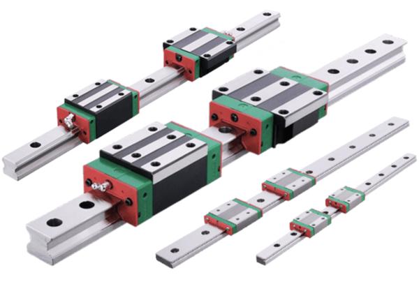
HIWIN Linear Guideways: The Ultimate Selection and Maintenance Guide (2026) In the world of precision automation, HIWIN linear guideways have become the industry standard for achieving high-positioning accuracy and smooth linear motion. Whether you are retrofitting a CNC machine or designing a high-speed semiconductor assembly line, choosing the right series is a balance between load capacity, space constraints, and environmental factors. 1. Understanding the Core Technology A HIWIN linear guideway consists of a profile rail and a bearing block (carriage). The magic happens within the block, where recirculating rolling elements (balls or rollers) minimize friction to a coefficient of roughly 1/50th of a traditional sliding guide. Why HIWIN? Equal Load Capacity: Most series (like the HG and EG) are designed to handle loads in radial, reverse-radial, and lateral directions equally. Self-Alignment: HIWIN’s circular-arc groove design can absorb small installation errors, ensuring smooth motion even if the mounting surface isn't perfectly flat. Interchangeability: High manufacturing standards allow you to replace blocks or rails independently while maintaining precision. 2. Choosing the Right Series: A Comparison Not all linear guides are created equal. Using an oversized rail wastes money and space, while an undersized one leads to premature “pitting“ or failure. Series Type Primary Feature Best For HG Ball Heavy load, high rigidity CNC machines, grinding, heavy-duty lathes. EG Ball Low profile, compact Packaging, high-speed automation, robotics. RG Roller Extreme rigidity Heavy cutting, high-precision milling. MG Ball Miniature, stainless steel Medical devices, semiconductor, 3D printers. WE Ball Wide rail, high moment Single-axis applications with high torque. Technical Insight: Balls vs. Rollers The HG series uses steel balls, providing a “point contact“ that excels in speed and lower friction. The RG series uses cylindrical rollers, creating a “line contact.“ This significantly increases the contact area, reducing elastic deformation and making it the “gold standard“ for heavy-duty industrial machining where vibration must be zero. 3. High-Tech Options: SynchMotion™ & Cover Strips For advanced 2026 applications, two specific HIWIN innovations are worth the investment: SynchMotion™ (QH/QE/QR Series): These blocks include a “ball separator“ between the rolling elements. This prevents ball-to-ball friction, leading to quieter operation, higher speeds, and longer lubrication intervals. Cover Strips (CG Series): Traditional rails have mounting holes that can collect dust. The CG series features a stainless steel cover strip that snaps over the rail, providing a completely smooth surface for the seals to glide over, drastically extending life in “dirty“ environments like woodworking. 4. Maintenance: The “100km Rule“ Most end-user failures are not due to load, but lack of lubrication. Lubrication Schedule Linear guides should be relubricated every 100km of travel or every 3 to 6 months, whichever comes first. If you are operating in a high-dust environment (e.g., carbon fiber routing), this interval should be halved. Tips for Longevity: Check the Wipers: If the rubber end-seals on your block look cracked or worn, replace them immediately. A $10 seal protects a $500 rail system. Grease Type: Use a lithium-soap-based grease (like HIWIN G05) for general applications. Avoid mixing different types of grease, as chemical incompatibility can cause the lubricant to harden. Initial Pre-greasing: New blocks often come with only a light coat of anti-rust oil. Always perform an initial lubrication before running the system under load. 5. Avoiding Common Installation Mistakes Expert experience shows that alignment is everything. The Master Rail: Always designate one rail as the “master“ and align it to a reference shoulder on your machine bed. The “subsidiary“ rail should then be aligned relative to the master. Torque Spec: Use a calibrated torque wrench. Over-tightening mounting bolts can slightly deform the rail, causing “binding“ and localized wear. Parallelism: For a dual-rail setup, parallelism should usually be within 0.01mm to 0.05mm (depending on the series and preload). Pro Tip: If your machine “shudders“ or makes a clicking sound at certain points, it’s likely a parallelism issue. Loosen the subsidiary rail bolts, run the carriage across the full stroke, and re-tighten. Conclusion HIWIN linear guideways offer a versatile, high-performance solution for almost any motion challenge. By matching the series (HG for power, EG for speed, RG for stiffness) to your specific needs and sticking to a rigorous lubrication schedule, you can ensure your machinery operates with micron-level precision for years.

68179d65be22ee500d53ff54 Card 2

product image
Pisco Pneumatic

Gemini said High-Performance Vacuum Suction Cups: The Heart of Robotic Automation In the world of high-speed packaging, the smallest component often carries the heaviest load. Vacuum suction cups are the critical interface between a robotic arm and the product, determining the speed, safety, and reliability of an entire production line. Precision Engineering for Packaging Whether you are handling porous cardboard, flexible pouches, or delicate glass, selecting the right material is paramount. Silicone: Ideal for extreme temperatures and food-grade applications. Nitrile (NBR): The workhorse for oily environments or heavy-duty wear. Polyurethane: Offers maximum tear resistance for high-friction movements. Optimizing Robotic Efficiency Modern vacuum suction cups for robots are designed to minimize “cycle time.“ Using bellows-style cups provides a “lifting“ effect that compensates for height differences and uneven surfaces, while flat cups offer the stability needed for high-acceleration “pick and place“ tasks. +1 Why EEAT Matters in Vacuum Technology When sourcing industrial components, Experience and Expertise are non-negotiable. Using sub-standard cups leads to “drop incidents,“ increasing downtime and cost. Leading manufacturers now integrate sensing technology directly into the vacuum manifold to provide real-time feedback on seal integrity.

68179d65be22ee500d53ff54 Card 2

product image
Pisco Pneumatic

Suction Cups for Packaging Automation Packaging lines are notorious for high cycle speeds and dusty environments. When selecting cups for this sector, consider: Porosity Handling: Cardboard is naturally porous. To maintain a grip, you need high-flow vacuum generators or cups with specialized foam seals. Food Safety: If the cup touches raw or packaged food, it must be FDA-compliant and often “detectable“ (impregnated with metal fragments) so it can be caught by X-ray scanners if a piece breaks off. High-Speed Stability: In “delta“ style picking robots, the cup must resist lateral forces to prevent the product from swinging or dropping during rapid directional changes.